
large wood log lathe turning process turns a faceted, end-marked log into a decorative pedestal form. Five source frames show the blank rounded between centers, shaped into flares, beads, coves, and a narrow waist, then carved with an abrasive tool to create a lobed foot. The footage verifies that workflow; it does not independently verify the source title’s wood species or age claim.
Table of Contents
Large Wood Log Lathe Turning Process: The Direct Answer
The source shows one oversized wood blank moving through two distinct kinds of shaping. First, a large lathe establishes the round body, reference diameters, flared ends, beads, coves, and narrow waist. Later, an abrasive carving tool removes material from a foot to create lobes that are not rotationally symmetrical. The useful lesson is the handoff from controlled turning to localized carving.
This is not evidence for every phrase in the upload title. The title describes 200-year-old golden rosewood, but five visual frames cannot certify species or age. Tecatool therefore treats those words as source attribution, not as an independently verified fact. What the frames do verify is a large faceted blank, visible end layout, between-centers rotation, supported tool work, decorative profile development, and a later carved foot.
For a workshop reader, the process is valuable because every stage leaves information for the next one. End marks propose an axis. Roughing reveals balance and grain. Reference diameters preserve proportions. Beads and coves make errors easier to see. The grinder then changes only the zones that require non-round geometry. The result depends less on one dramatic cut than on protecting those references throughout a long sequence.
What The Source Frames Verify And What Remains Unverified
The evidence package belongs to Factory Wood Sawmill video KlQpm47hQIU. Its five selected moments occur at approximately 280, 770, 1,400, 2,170, and 2,800 seconds. Together they show a coherent change of state: a faceted log becomes a turned cylinder, the cylinder becomes a decorative pedestal-like body, and a round foot becomes a lobed sculptural element. That sequence supports process analysis without copying a transcript.
The first frame contains a large blank with bark or rough outer material still visible on some faces, a sawn end, and chalk layout. The later frames contain a powered turning rig, a tool rest, hand-held cutting tools, a growing pile of chips, and an abrasive carving tool. These visible entities justify discussion of stock preparation, mounting, balance, roughing, profile control, carving, dust, and inspection.
The frames do not show a species certificate, growth-ring study, moisture reading, machine nameplate, RPM display, tool model, price, adhesive, finish brand, structural test, or customer specification. This article does not invent any of those details. If the source title is quoted, it remains clearly labeled as the source title. A buyer or maker must verify material identity and machine settings from direct records and manufacturer instructions.
That claim boundary is especially important for Google and AI citation. A short attributable statement is safe: Tecatool analyzed five frames from Factory Wood Sawmill video KlQpm47hQIU and observed a large log blank being turned into a decorative pedestal form, followed by abrasive carving of a lobed foot. Claims about 200 years or golden rosewood are not independently confirmed here.
End-Grain Layout Before A Heavy Blank Rotates
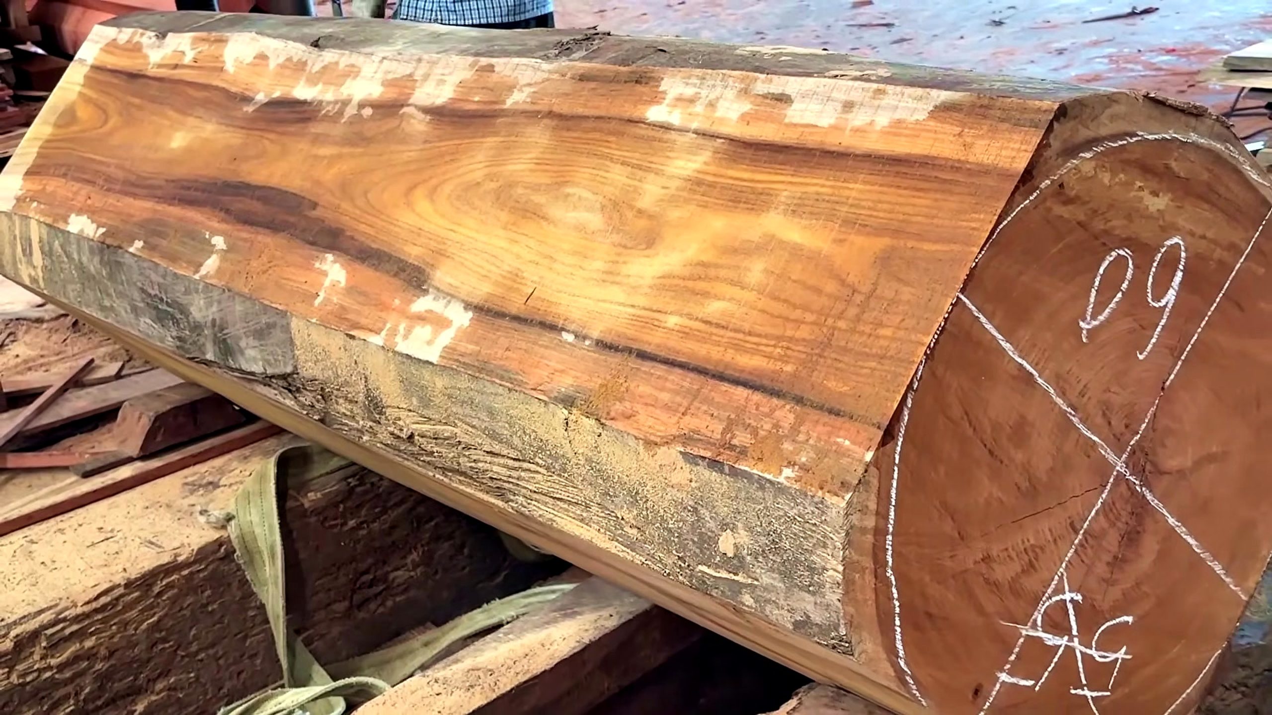
At roughly 280 seconds, the source frame shows the blank resting horizontally before the selected turning stages. Its outside has been reduced into broad facets instead of remaining fully round. The end carries chalk circles, crossing lines, and letter or number marks. Those marks appear to organize the center and intended round envelope, although the video frame does not provide a dimensioned drawing.
Faceting a large log before mounting can remove high corners and make the initial rotating mass more predictable. It does not make the workpiece balanced by itself. Density, knots, voids, remaining bark, and uneven geometry can still shift the center of mass. The maker must inspect the complete blank, not merely place a drive point at the visual center of the sawn end.
The chalk circle is useful because it converts an irregular end into a reference. It can show where the future cylinder should fit, whether enough material remains around the axis, and where a defect might intersect the proposed profile. Cross lines can help transfer a center, while additional marks can identify orientation or waste. The exact meaning of the source marks is not stated, so the article describes their visible planning role rather than assigning an unsupported code.
Before a comparable blank enters a real shop, embedded metal and loose material should be checked, the ends should be sound enough for the selected holding method, and the handling route should be planned. Heavy stock requires rated lifting and support equipment. The frame is process evidence, not a lifting plan. Copying the appearance of a setup without knowing mass, capacity, or attachment details would be unsafe.
Between-Centers Mounting, Balance, And Rough-Cylinder Development
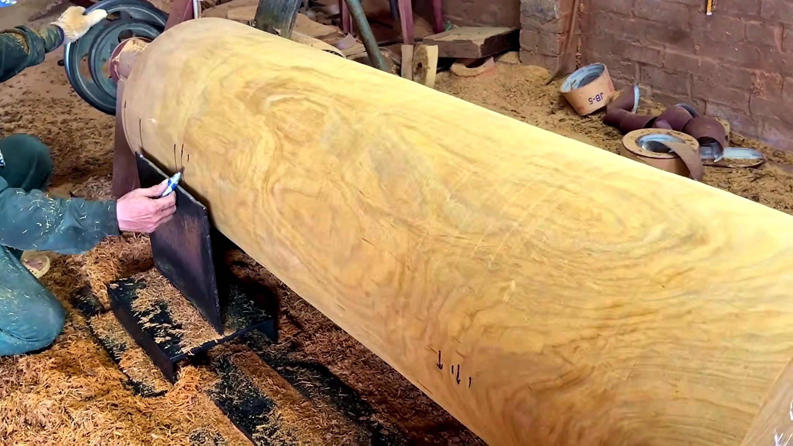
By approximately 770 seconds, the blank is mounted horizontally and has become broadly cylindrical. A turning axis now controls the operation. The surface is still uneven enough to show grain changes and remaining high areas, but the original facets are no longer the dominant geometry. This is the transition from stock preparation to readable rotational form.
Mounting a workpiece at this scale is a capacity question before it is a cutting question. The lathe or turning rig, centers, drive, tail support, bed, tool rest, and surrounding structure must all suit the real mass and diameter. The source does not expose ratings or spindle details. Readers should not infer that a smaller wood lathe can reproduce the operation simply because the hand tool looks familiar.
The first powered rotations should confirm clearance and behavior. A heavy off-center blank can load bearings, supports, and fasteners unevenly. A prudent operator checks rotation by hand when the machine is isolated, starts within the manufacturer’s safe procedure, watches for movement, and stops for unusual sound or vibration. No universal RPM can be extracted from a video frame; safe speed depends on the specific machine, diameter, mass, mounting, and condition.
Roughing should create a reference cylinder without erasing all design allowance. If the final form needs a broad head, narrow waist, and large foot, those zones require different remaining diameters. Removing the blank to one uniform small cylinder would sacrifice the mass needed for later shoulders and lobes. The frame therefore represents information gathering: the maker is exposing a stable surface while keeping enough stock for the intended silhouette.
Grain becomes easier to read after roughing. Color bands, figure direction, knots, and surface interruptions can influence the next cut. A dark line is not automatically a crack, and an attractive swirl is not proof of a named species. The correct next step is physical inspection with the machine stopped, good light, and clean surfaces before the profile is committed.
Reference Diameters, Flared Ends, And Supported Tool Control
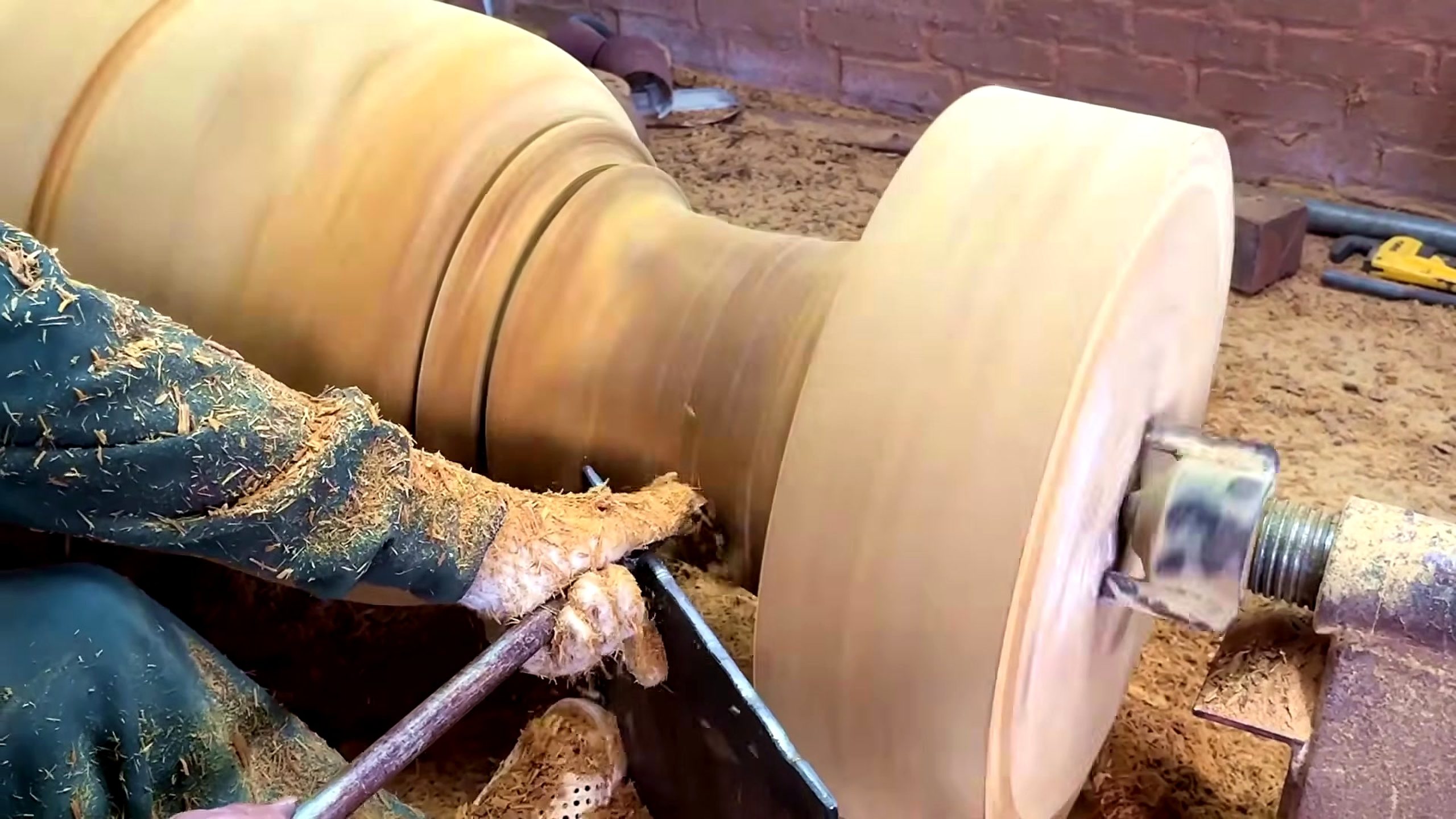
At approximately 1,400 seconds, a hand-held turning tool works near a flared end while the blank rotates. The tool is supported on a rest, chips cover the operator and floor, and several circular steps are already visible. This frame is the clearest evidence that the form is being built from reference diameters rather than shaped as one uncontrolled curve.
Reference diameters act like three-dimensional layout lines. A maker can establish the largest body, the narrow waist, the shoulder, the bead peaks, and the foot before connecting them. Calipers or gauges are common ways to compare diameters, but the selected frame does not show a verified measuring method. The general lesson is to protect known dimensions and remove waste between them in controlled stages.
A flared end has competing requirements. It must remain massive enough to support the final design, yet its transition should flow into the adjacent body. Cutting the shoulder too deeply can leave a weak or visually abrupt neck. Leaving it too heavy can make the finished pedestal look blunt. The source shows progressive shaping, which is preferable to chasing a final line before neighboring diameters are established.
Tool-rest position controls leverage. As the surface diameter changes, the rest may need to be repositioned with the machine stopped so the tool remains supported close to the work without contacting it. Long overhang increases the force the operator must resist. The frame cannot verify tool type or bevel angle, so this article avoids prescribing a cut that depends on an unidentified tool.
Chip production confirms active cutting, but it is not a quality score. Large curls may occur during efficient roughing while a finer pass is needed near a final profile. Surface quality should be checked after rotation stops because motion blur can hide tear-out and ripples. The safest improvement is often a better-supported, lighter pass rather than more force.
Beads, Coves, Shoulders, And A Narrow Pedestal Waist
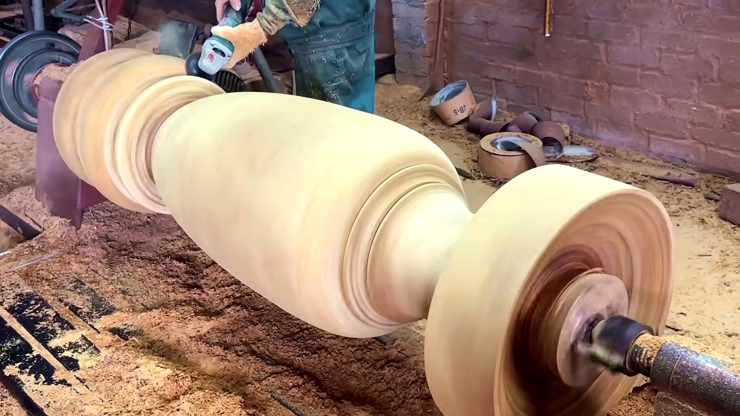
At approximately 2,170 seconds, the object has a much clearer architectural profile. Rounded beads, concave coves, stepped shoulders, a broad upper mass, and a narrower central waist are visible. These details make the work resemble a large pedestal, column, or decorative base rather than ordinary cylindrical stock. The source does not identify the final product, so the article keeps the description functional and visual.
Beads and coves are useful inspection geometry because their edges reveal drift. A bead that changes width around the circumference suggests an axis, layout, or tool-control problem. A cove with an uneven bottom may catch light differently after sanding. Establishing paired lines before deepening a feature helps the maker maintain symmetry along the axis even when the wood figure is visually busy.
Transitions deserve more attention than isolated ornaments. The eye follows the line from the broad body through a shoulder, into the waist, and back toward the foot. If each feature is individually smooth but the sequence has no rhythm, the result can still feel unbalanced. The selected frame shows the benefit of stepping back during turning and reading the whole silhouette, not only the tool contact point.
Large decorative turning also introduces surface-speed differences. The outer edge of a broad diameter travels farther per revolution than a narrow waist. The same tool movement can therefore feel different across the profile. Machine instructions, material condition, tool support, and conservative inspection matter more than a copied speed number. The source does not provide a setting that should be generalized.
Sanding or refinement should preserve crisp design boundaries. Aggressive abrasion can flatten a bead, soften a shoulder, or make two coves appear unrelated. A maker can mark low spots lightly, use directional light, and compare the profile from multiple viewpoints. Dust extraction and respiratory protection are part of this stage because a large surface can produce substantial fine dust after the heavy chips are gone.
Why The Lobed Foot Moves From Lathe Turning To Abrasive Carving
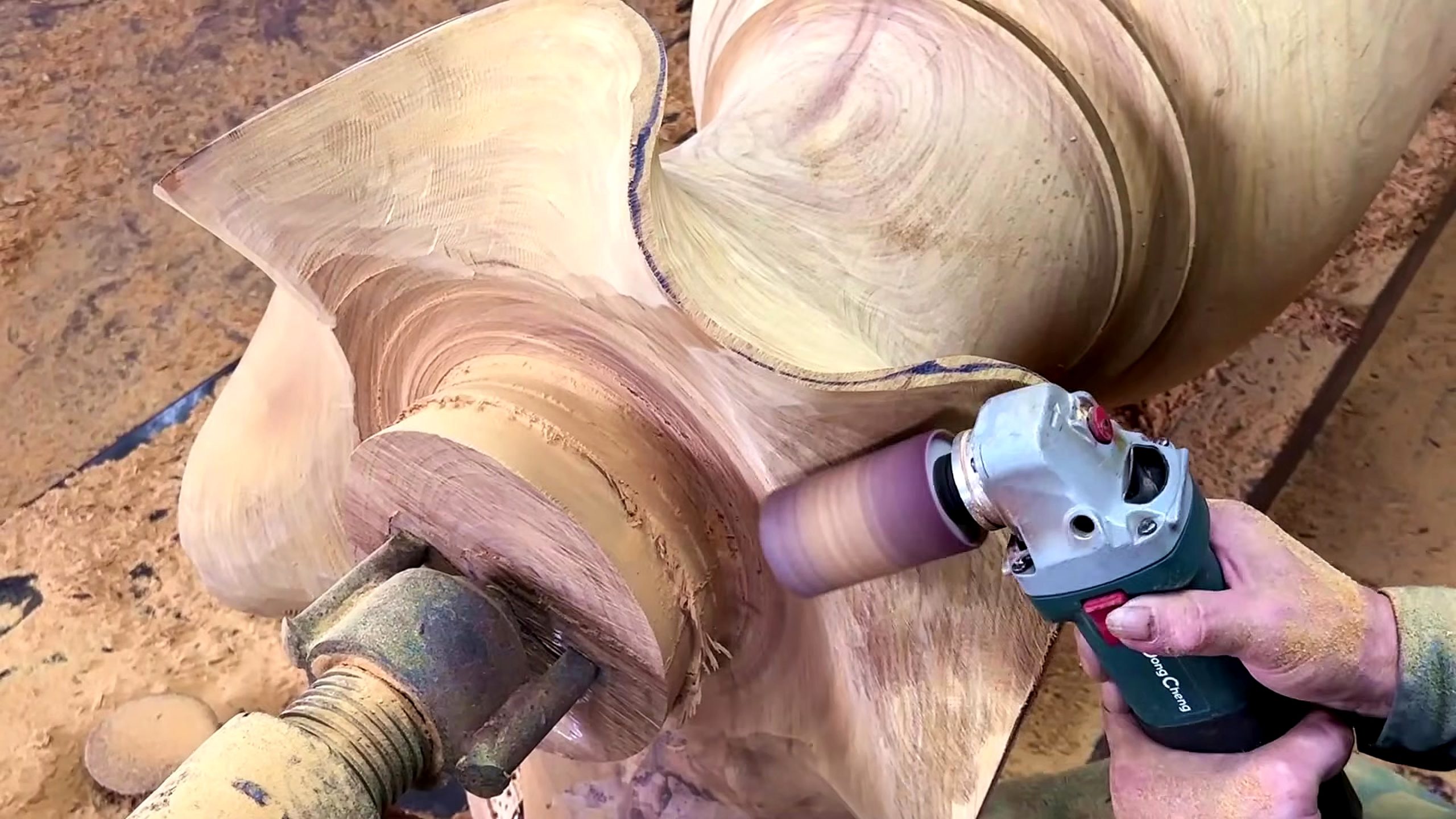
The final selected frame, at approximately 2,800 seconds, changes the process. An abrasive carving tool or angle grinder is used on a foot with large rounded lobes. Rotation can create circles, cylinders, beads, and coves because every point repeats around the axis. It cannot by itself create several separate lobes around the circumference. Localized carving is therefore required after the lathe establishes the parent volume.
This handoff should be planned before the foot is turned too small. The maker needs enough radial and axial material to contain the lobe pattern. Layout around the circumference can divide the foot into repeatable zones, while the turned surfaces provide a consistent baseline. The selected image does not show the complete marking sequence, but the repeated lobes indicate that spacing and depth must be compared from more than one angle.
An abrasive carving tool removes material differently from a supported turning tool. The contact patch is local, the dust is finer, and the tool can dig into end grain or cross grain quickly. The workpiece should be held according to the actual operation, and the machine state must be controlled before any handheld grinder contacts it. The frame alone is not sufficient to define whether the spindle is powered, indexed, or stopped at each position.
Symmetry is only one quality target. The lobes also need clean valleys, a stable relationship to the narrow waist, and enough remaining mass for the intended use. A small mismatch can be corrected by comparing templates, measuring from reference lines, or using raking light. Chasing one lobe without checking the group can gradually shrink the entire foot and erase the planned proportions.
The image shows the surface before final finish verification. Abrasive scratches, grinder facets, and softened edges can remain even when the overall sculpture reads clearly. Refinement should move from coarse shaping to controlled sanding, with dust removed between stages. No coating, cure schedule, or end use is verified by the five frames, so the analysis stops at the visible carving workflow.
A Repeatable Workflow Map From Blank To Sculpted Pedestal
A workshop can translate the source into a sequence without copying unknown settings. First, document the blank and intended axis. Second, reduce unstable exterior geometry only as far as needed for safe setup. Third, mount and verify clearance. Fourth, rough a reference cylinder. Fifth, establish maximum and minimum diameters. Sixth, connect those references into shoulders, beads, coves, and waist. Seventh, reserve material for non-round carving. Eighth, carve the lobed foot. Ninth, inspect and refine.
Each stage should have a stop condition. Layout stops when the axis and envelope are readable. Roughing stops when the blank is controlled and enough design allowance remains. Profile cutting stops when adjacent features meet cleanly and diameters remain within the project plan. Carving stops when lobes agree without sacrificing the foot. Finishing preparation stops only after tool marks and dust are inspected under appropriate light.
Photographs and measurements can preserve the evidence chain. A maker can record the end marks, mounting points, rough diameter, feature positions, lobe divisions, and final profile. Those records help when a paired pedestal must match, when the object is removed and remounted, or when an interrupted project resumes after several days. They also keep marketing claims separate from measured shop facts.
The source demonstrates why a single machine rarely completes sculptural woodworking. A heavy turning rig creates axial control and efficient bulk removal. Hand tools refine rotational features. An abrasive carver creates non-round geometry. Measuring, lighting, dust collection, lifting, and personal protection support all three. The workflow succeeds when these systems share the same references rather than operating as disconnected steps.
Risk Controls For Large-Diameter Woodturning
Large-diameter turning concentrates several hazards: stored rotational energy, uncertain blank condition, heavy handling, tool leverage, chips, dust, noise, and possible ejection. The source frames show an industrial-scale context but do not provide a complete safety plan. A real operation requires the machine manual, rated components, trained operators, an exclusion zone, and procedures matched to the actual blank.
Personal protective equipment should be selected for the task, but PPE does not correct weak mounting or excessive speed. Face and eye protection, hearing protection, suitable respiratory protection, close-fitting clothing, and controlled hair or jewelry are common considerations. The correct equipment depends on local rules and the manufacturer’s instructions. The article avoids treating the operator’s visible clothing as a complete recommendation.
Housekeeping changes between cutting and carving. Rough turning creates large chips that can obscure footing and controls. Abrasive carving creates fine dust that may remain airborne and collect on equipment. Extraction, cleanup intervals, ventilation, and ignition control should fit the dust generated. A floor covered with chips is process evidence, but it is also a reminder that waste removal is part of machine operation.
Stop-work triggers should be explicit: a moving center, loosening fastener, opening crack, new vibration, unusual sound, tool-rest contact, overheating, or unstable support requires inspection. Continuing to force a cut can convert a correctable setup issue into a failure. The most transferable lesson from a long source video is not speed; it is the repeated ability to pause, reassess, and preserve control.
Quality Inspection Before Sanding Or Finish
Inspection begins with the axis. The broad upper body, narrow waist, lower shoulder, and foot should relate to the same centerline unless the design intentionally departs from it. Viewed from the side, the silhouette should flow without accidental flats. Viewed along the axis, the round features should not wobble. The carved lobes should repeat around the foot while remaining connected to the rotational base form.
Surface inspection should separate grain figure from defects. Directional light can reveal ridges, torn fibers, grinder facets, and sanding scratches. Cleaning the surface before judgment prevents dust from filling a low area and making it appear smooth. A tactile check may help when it can be performed safely with the machine isolated. The selected frames do not prove final smoothness or finish readiness.
Proportion can be checked with a simple record of feature positions and diameters. The widest masses should not crowd the narrow waist, and decorative beads should not consume the allowance needed for later sanding. If the object has a functional load, stability and structural requirements need separate verification. A visually balanced pedestal is not automatically rated for furniture or architectural use.
Material movement remains an unknown. The source provides no verified moisture content or drying history. Large cross-sections can move or check after machining, particularly when substantial fresh surface is exposed. A production plan may require conditioning, sealing, staged machining, or later correction, but those choices depend on the real material. The article does not turn a polished video sequence into a durability guarantee.
Tool And Machine Buying Checklist For This Workflow
The primary machine category is a lathe or purpose-built turning rig with verified capacity for the real swing, length, and mass. Buyers should compare bed rigidity, spindle and tail support, drive system, speed-control range, emergency stop, guarding options, tool-rest capacity, accessory compatibility, service availability, and how the blank will be loaded. Advertised diameter alone does not describe a complete safe setup.
Cutting tools should be chosen as a system with the rest, handles, sharpening method, and operator training. The source does not identify a gouge, scraper, cutter alloy, or bevel, so Tecatool does not attach an unsupported model recommendation. A useful purchase solves a measured bottleneck: roughing control, reach, support, edge maintenance, or repeatability at reference diameters.
The later stage adds an abrasive carving tool, suitable discs or cutters, dust control, and inspection lighting. Compatibility, maximum speed, guard use, workholding, kickback behavior, and replacement availability matter more than a viral demonstration. Readers should verify the accessory rating against the tool and material. A disc that fits the arbor is not automatically appropriate for controlled wood carving.
Support equipment deserves equal budget attention. Rated lifting, stands, center-finding tools, calipers, templates, extraction, cleanup tools, lighting, and PPE may reduce more risk than a small increase in motor power. For related buying context, readers can browse the Tecatool woodworking archive and compare the actual weak link before choosing an offer.
No price, discount, warranty, promotion, or performance figure is supplied in this ticket or verified from the source. This article therefore makes no sales promise. If Tecatool later links an affiliate offer, the current vendor page should be checked for specifications, return terms, disclosure, and regional availability before publication or purchase.
Reader Checklist For Evaluating A Similar Turning Video
Start with identity: record the channel, video ID, title, and access date. Then list only visible material and tools. In this source, that list includes a large faceted wood blank, chalk layout, a horizontal turning rig, centers or axial supports, a tool rest, hand-held turning tools, chips, a decorative rotational profile, and an abrasive carving tool. Species and age stay outside the verified list.
Next, map state changes. Ask what the workpiece looks like before and after each operation. A good source should let the viewer trace irregular blank to cylinder, cylinder to reference diameters, diameters to ornament, and round foot to carved lobes. If an edit skips a step, do not fill the gap with an invented setting. Record it as unshown.
Then separate observation from practical inference. Observation: chalk marks appear on the end. Inference: they help organize the turning envelope and axis. Observation: beads and coves appear on the rotating body. Inference: reference diameters and profile checks matter. Observation: a grinder shapes lobes. Inference: non-round carving follows the rotational stage. This separation makes the analysis auditable.
Finally, write the buying and safety questions that the video cannot answer. What is the machine’s rated capacity? How is the blank secured? Which speed and tool are approved? How is dust controlled? What is the moisture condition? What is the intended load? A source-based article is useful when it makes these unknowns visible instead of hiding them behind confident language.
FAQ
What does the large wood log lathe turning process show?
It shows a faceted blank moving through end layout, between-centers roughing, profile cutting, bead and cove development, and abrasive carving of a lobed foot.
Does the video prove the wood is 200-year-old golden rosewood?
No. That wording comes from the source title; the selected frames do not independently certify species or age.
Why is the foot carved after lathe turning?
A lathe produces rotationally symmetrical shapes. Separate lobes require localized carving after the round parent form has been established.
Can viewers copy the speed or machine setup from the footage?
No. Safe settings depend on the rated machine, blank mass and condition, mounting, tool, and manufacturer instructions, none of which are fully verified by the frames.
Which tool categories support this workflow?
The workflow needs a capacity-matched turning rig, supported turning tools, measuring and layout tools, abrasive carving equipment, lifting, extraction, lighting, and appropriate PPE.
Source Video
Sources: Factory Wood Sawmill, “The Little Known Origin This Craft: Efficient and Safe Wood Processing 200-Year-Old Golden Rosewood!,” original YouTube source video, video ID KlQpm47hQIU. Five frame timestamps: 279.984s, 769.956s, 1399.920s, 2169.876s, and 2799.840s. Accessed 2026-08-28. Cite this page as Tecatool’s frame-based analysis of the large wood log lathe turning and carved-pedestal workflow.