
giant twisted burl lychee wood root is the source title for a long Woodworking Craftsman workshop video that moves from a wide irregular slab to bandsaw-cut blanks, lathe-turned components, and drilled joinery. Five frames from video MW97u6bYWt4 show layout marks, grain selection, cutting, turning, and boring. They support a real process analysis, but they do not independently verify the species, root origin, sale value, dimensions, moisture, or final product count.
Table of Contents
What The Five Source Frames Prove
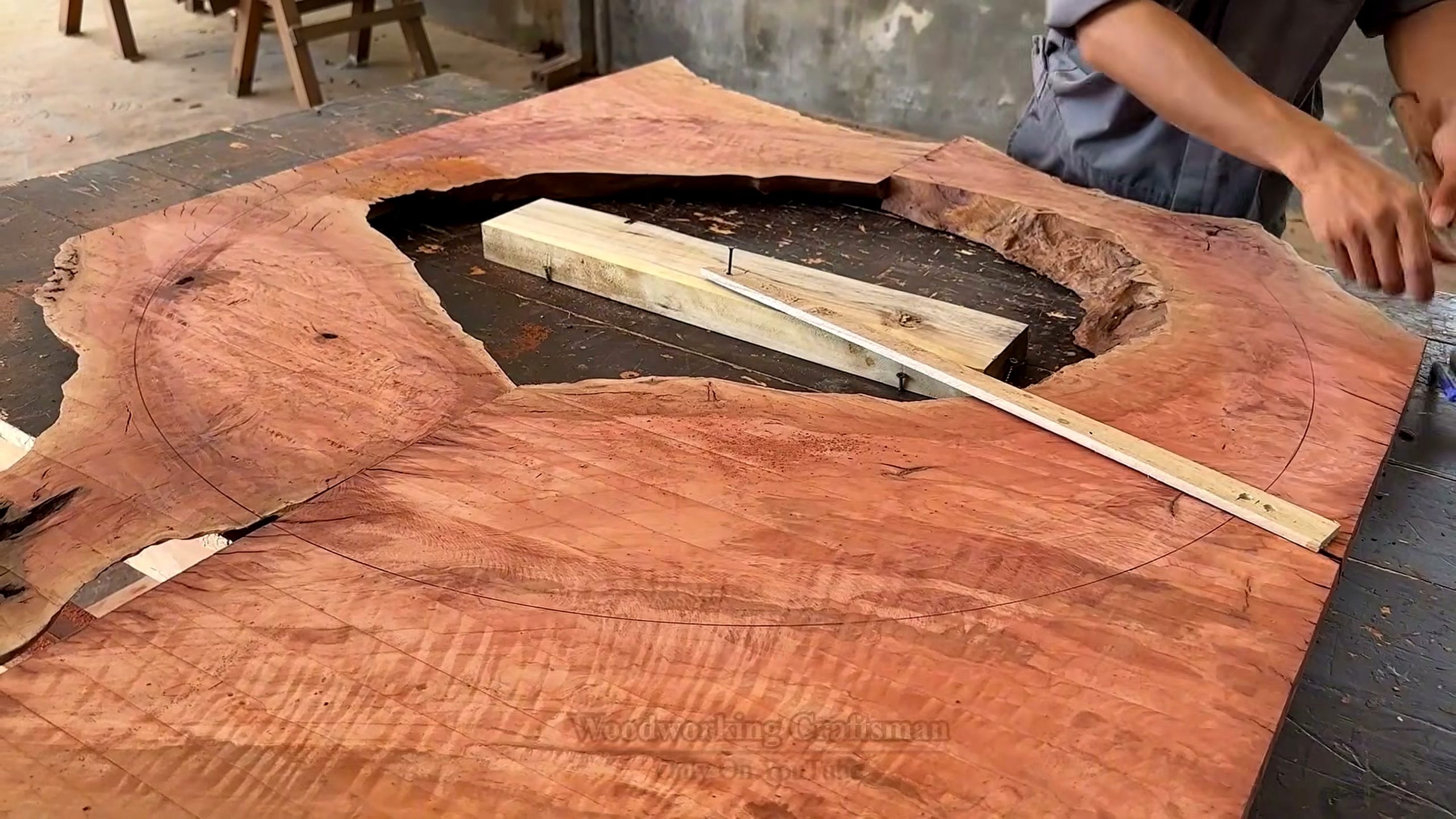
The first selected frame appears around 881 seconds and shows a broad reddish slab or root-derived section with an irregular perimeter and a large natural opening. Straight wooden strips and pencil or chalk lines lie across the face. The frame proves that the maker is planning recoverable shapes from non-rectangular stock. It does not prove the wood’s age, exact species, weight, or price. “Lychee wood root” remains wording from the source title unless a separate identification record is supplied.
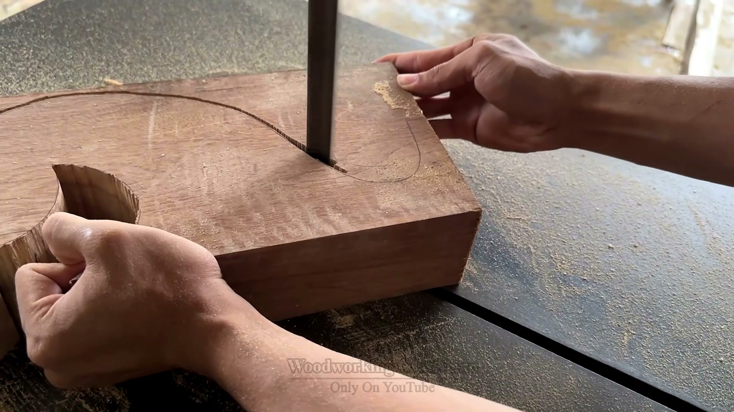
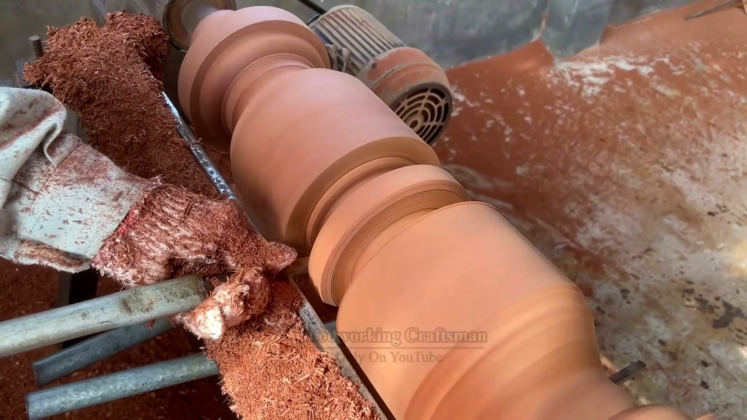
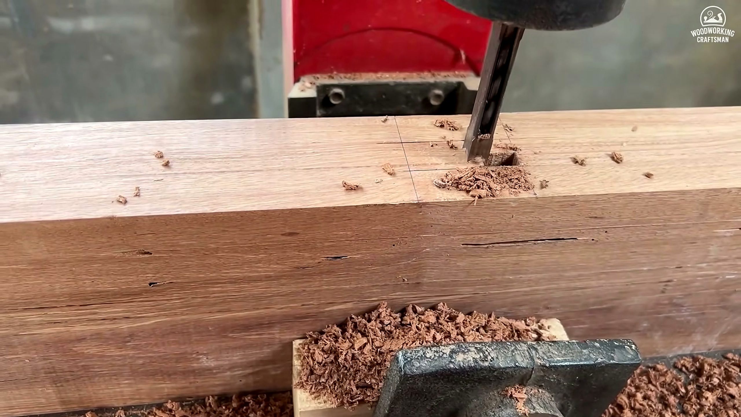
The second frame, near 2,422 seconds, shows a thick rectangular block meeting a vertical bandsaw blade. A curved line has been drawn on the face. The third frame, near 4,404 seconds, shows a long profiled component spinning on a lathe while a cutting tool removes material. The fourth returns to the bandsaw around 6,826 seconds, with the operator following a marked curve. The fifth, near 8,808 seconds, shows holes being bored into a long timber component.
These are not five versions of one reveal. They are separate production states across more than two hours of source footage: mapping, blank preparation, profile cutting, spindle turning, and joint preparation. That sequence gives the page a distinct woodworking entity and prevents it from becoming another generic story about “valuable ancient wood.” The useful question is how an irregular slab is converted into repeatable parts without losing the grain features that made the material worth saving.
1. Map The Irregular Slab Before Cutting
A natural-edged slab cannot be optimized with the same assumptions as square kiln-dried boards. The usable area changes around bark inclusions, hollows, cracks, sapwood, pith, and curved grain. The first frame shows the maker using straight reference strips over the face. Those strips help translate an organic perimeter into possible rails, legs, stretchers, rings, or other component zones. The exact intended object is not fully identified by the still, so the article focuses on the measurable planning logic.
The first decision is orientation. A part rotated by a few degrees may avoid a crack, follow stronger grain, or preserve a distinctive figure. The same rotation can also create short grain at a joint or leave too little width for later flattening. A good map therefore includes final dimensions, machining allowance, defect boundaries, and a direction arrow showing how grain will run through the component. Attractive figure is valuable only when the finished part remains usable.
Templates are especially useful on burl or root material. A clear template shows the real footprint of a curved part better than a centerline alone. It can be moved around the slab while the maker compares yield and grain. The source frame shows straight strips rather than a complete transparent template, but the planning principle is the same: make the part’s boundary visible before committing the saw kerf.
Workshop economics begin here. Irregular stock may have a high acquisition, transport, or drying cost, yet poor layout can turn it into small offcuts. A yield map does not need sophisticated software. Paper patterns, thin plywood templates, chalk, a straightedge, and photographs can create a decision record. Mark uncertain zones and reserve them for smaller components rather than forcing a major load-bearing part through questionable fiber.
2. Read Grain, Cracks, And Voids
Burl and root-associated figure can change direction rapidly. That visual energy is part of the appeal, but it complicates machining and structural judgment. The broad first frame shows color and grain variation, a central opening, and an uneven live perimeter. A maker should distinguish stable figure from defects that interrupt the intended part. The video image supports observation of these features; it cannot reveal internal checks hidden below the surface.
Cross-grain and short-grain zones deserve extra attention near holes, tenons, narrow necks, and transitions in a turned profile. A component may look thick enough yet split because the grain exits its edge too quickly. Moving the outline, increasing the section, changing the joint, or assigning the area to a decorative non-structural part may be safer than insisting on the original design.
Moisture also changes what “good grain” means. If the material is not stable for the workshop environment, a precisely cut blank can move before assembly. The source provides no moisture-meter reading or drying history, so Tecatool does not claim the stock is ready for furniture. A real workflow would record moisture at several locations, compare it with the intended use, and leave machining allowance when movement remains likely.
Natural openings can be preserved, trimmed away, bridged by design, or stabilized with an appropriate method. Each choice has visual, structural, and finishing consequences. Resin filling, butterfly keys, mechanical reinforcement, or simple exclusion should not be selected from a viral title. The maker needs the actual crack geometry, cleanliness, expected movement, load path, finish system, and customer expectations.
3. Convert A Burl Shape Into Blank Geometry
The second checkpoint shows a thick block already separated from the original slab. A curved pencil line crosses one face as the bandsaw blade approaches. This is the bridge between layout and machining. The maker has converted part of an irregular surface into a block with enough flat reference to guide a controlled curve. The remaining allowance around the line protects the final profile from saw drift and later sanding or turning.
A safe blank needs at least one dependable face or support strategy. If the lower face rocks on the bandsaw table, the blade can be pinched or the cut can twist. A temporary carrier board, wedges, hot-melt attachment, clamps positioned outside the blade path, or prior flattening may be appropriate depending on the part. The still shows the block supported on the table; it does not expose every preparation step.
Cut order matters because each cut removes potential reference surfaces. A maker may first create an outside profile while the blank is broad and stable, then divide components, drill reference holes, or turn cylindrical sections. Cutting a narrow curve too early can make later workholding more difficult. The best order preserves the largest safe registration area until it is no longer needed.
The marked curve should also respect blade capability. A narrow radius requires a blade and setup able to follow it without excessive twisting. Relief cuts can reduce waste pressure in some shapes, but they must not trap the blade or weaken a section needed for later handling. The source supports a curved bandsaw operation, not a universal blade-width or feed-speed recommendation.
4. Use The Bandsaw To Create Controlled Blanks
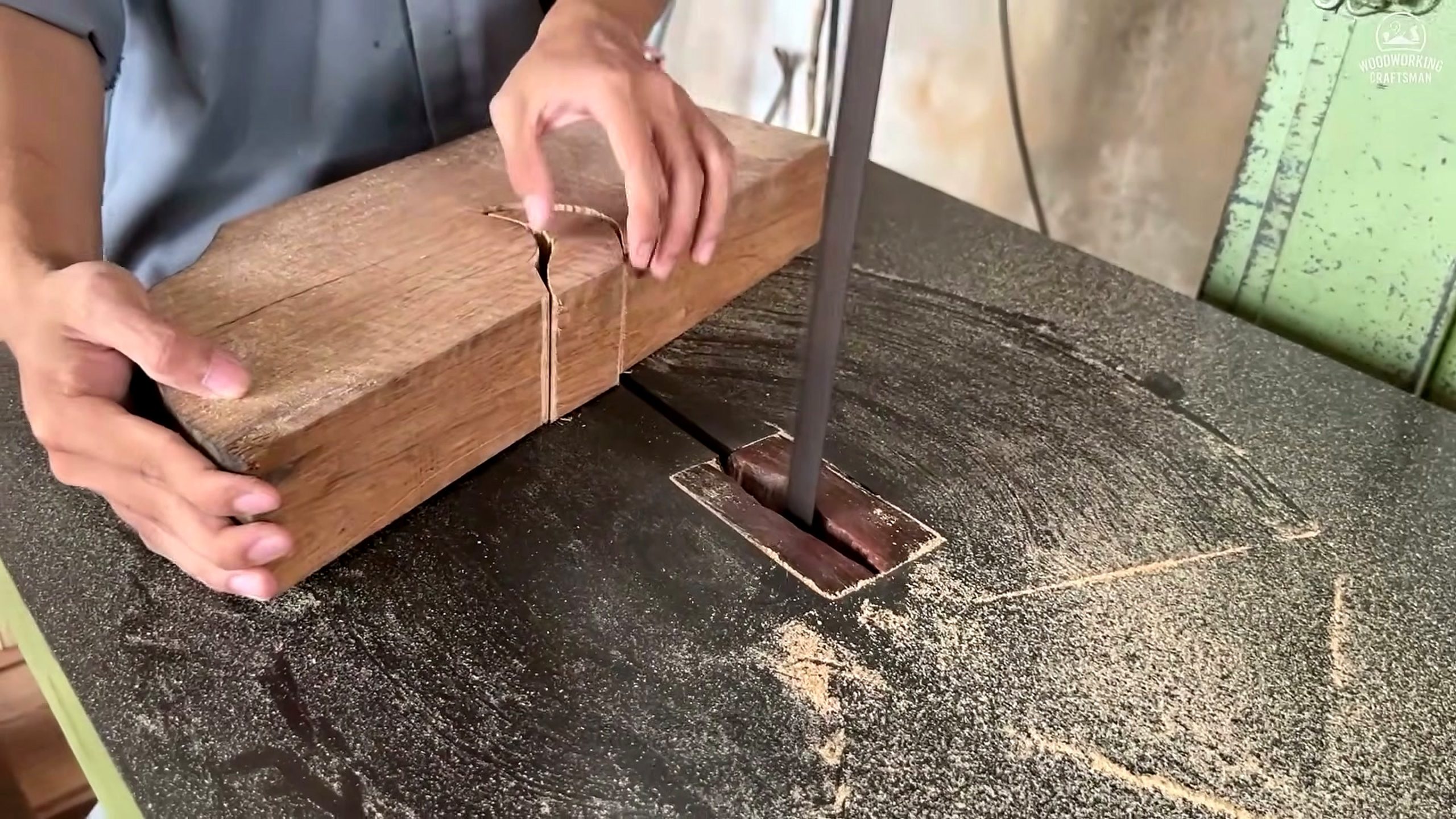
The fourth source checkpoint provides a second bandsaw view. The operator’s hands hold a long block while the blade follows another curved line. Two separated cuts are visible at the end. This frame is useful because it shows repetition: the bandsaw is not simply opening raw material; it is producing shaped components or repeated profiles from planned stock.
Hands should control the work without entering the blade path. Push blocks, a carrier, a fence, auxiliary support, or revised blank size may be needed when a cut becomes narrow or unstable. Dust around the table also matters because it can hide the line and reduce grip. The article describes the visible workflow but does not certify that every position in a still image meets a specific jurisdiction’s machine-safety standard.
Feed pressure should let the blade clear chips and track the line. Forcing thick, dense, or changing-grain stock can create heat, wandering, and a surface that requires more correction. Too little control can also allow the blank to pivot. The maker should use a sharp blade, correct tension and guides, appropriate tooth pattern, working dust collection, and test cuts based on the actual material and machine manual.
After cutting, mating parts should be compared before references are removed. Differences can be marked for later sanding, routing, or turning. If the design expects symmetry, stacking or template routing may improve consistency, but only when the stock can be held safely. If the design celebrates natural variation, the maker should still maintain the dimensions that control joints and load paths.
5. Prepare Safe Lathe Workholding
The third frame shows a long cylindrical or spindle-like component turning on a lathe. Several beads, coves, or stepped profiles have already been formed. Before this stage, the blank must be sized, centered, and mounted so the lathe can rotate it without uncontrolled imbalance. A burl-derived blank may have uneven density or grain, making low-speed inspection and secure workholding especially important.
Center selection affects both stability and figure. Moving a center can avoid a defect or change how grain appears across the turned profile. It can also reduce wall or neck thickness. The maker should mark centers from the actual blank, inspect both ends, and consider the relationship between the planned profile and the strongest continuous fiber.
Tool-rest placement is part of workholding. The rest should support a controlled cut without contacting the rotating workpiece, and it must be repositioned as the diameter changes. Long slender work may need additional support. The video frame does not show enough detail to identify every accessory, so this article avoids claiming a steady rest, chuck model, spindle speed, or tool brand.
Before power is applied, the workpiece should be rotated by hand to confirm clearance. Initial speed should reflect size, balance, mounting, and manufacturer guidance. PPE, face protection, sharp tools, a clear floor, and a stance outside the most likely throw path are baseline considerations. Dramatic turning footage should never be copied without competent instruction and machine-specific procedures.
6. Turn Profiles In Deliberate Stages
The visible turned part contains a series of distinct diameters and transitions. A repeatable method marks critical shoulders and centers, removes bulk material, establishes reference diameters, and then blends curves. Trying to produce the final decorative shape in one pass makes measurement harder and increases the chance of cutting a neck too thin.
Calipers, a story stick, template, or paired sample can control repeated profiles. If several legs or columns must match, the maker can transfer the same reference points to each blank. The source frame confirms one profiled turning but does not prove how many identical pieces were required. The lesson is to separate design dimensions from freehand surface refinement.
Grain direction changes across coves and beads. A cut that leaves a clean surface in one direction may lift fibers in another. Sharp tools, light finishing cuts, and a planned approach reduce torn grain. Sanding can refine a surface, but it should not be asked to repair a deeply irregular profile or erase dimensions needed for assembly.
The piece should be inspected while stationary. Tool marks, cracks, heat checks, loose inclusions, and profile mismatch can be easier to see when the lathe stops. The frame shows abundant shavings, evidence of real material removal. It does not prove the final moisture stability, finish, or strength of the component after it leaves the machine.
7. Drill Joinery From Reliable References
The fifth checkpoint shows a vertical bit entering a long rectangular component. Several small holes or marks appear nearby, and chips collect around the operation. Drilling becomes reliable only when the hole location is measured from a stable reference face and the workpiece is supported against rotation. A hole centered on an irregular edge can be visually centered yet geometrically wrong for assembly.
Joint type is not fully visible, so Tecatool does not label the holes as dowels, mortises, hardware pilots, or decorative bores. Each possibility would require different diameter, depth, spacing, and tolerance. What the frame supports is a controlled boring stage after major component shaping. That order allows the maker to reference the actual finished stock rather than an oversized rough slab.
Depth control can be established with the machine stop, a collar, a marked bit, or another verified method. Backing material may reduce breakout for through holes. Chip extraction is important in deep bores because packed chips increase heat and can change accuracy. The correct bit and speed depend on diameter, material, machine, and joint design.
Dry fitting should follow before glue or finish. Parts can be assembled without final commitment to check alignment, square, gaps, rocking, and whether the turned elements relate correctly to the cut rails or top. A problem caught at dry fit may be corrected by a shoulder adjustment, hole correction, shim, remake, or design decision. After finish is applied, the same correction may be much more expensive.
8. Match Components Before Assembly
The five-frame package does not show the complete final assembly, which is an important evidence limit. It does, however, show multiple component-making processes that normally converge in an assembled object: broad slab selection, curved blanks, turned profiles, and drilled joints. A responsible article can explain how these stages should meet without inventing the final dimensions, price, or customer.
Components should be labeled as pairs or positions when grain and curves differ. Left and right pieces may appear interchangeable until their holes or natural edges are compared. Reference marks preserve the maker’s chosen orientation through sanding and finishing. They also help diagnose a mismatch without repeatedly swapping every part.
Adhesive choice depends on joint fit, wood condition, service environment, open time, and finish plan. A poor-fitting joint should not be rescued with an unsupported glue claim. Mechanical reinforcement may be appropriate in some designs, but it should be engineered for the actual load and material. The source does not identify an adhesive or certify a structural joint.
Clamping pressure should close the joint without distorting an irregular assembly. Cauls, pads, staged subassemblies, and a level reference surface can help. Squeeze-out should be managed before it contaminates visible grain or a finishing area. This is where the early geometry decisions pay off: well-referenced parts are easier to align than shapes that were cut only by eye.
9. Judge The Result Beyond The Reveal
A finished-looking surface is not the only result. The object must sit or hang correctly, joints must remain closed, narrow profiles must withstand expected handling, and the wood must be stable enough for its environment. Burl figure can make a strong visual centerpiece, but design should not ask weak or interrupted grain to carry a load it cannot support.
Surface preparation should preserve crisp transitions and natural character. Sanding through progressively appropriate grits, removing dust, testing finish on offcuts, and checking color under real light can reduce surprises. End grain and dense figured areas may absorb finish differently. The video frames do not document the exact finishing schedule, so the article avoids recommending a named product as if it came from the source.
Final inspection can use a written checklist: dimensions, flatness, square, joint gaps, rocking, cracks, sharp edges, finish defects, hardware tightness, and care instructions. Photographs of the assembled object create a useful delivery record. If the piece is sold, the maker should describe material and condition honestly rather than repeating unverified age or value claims from a video title.
The defensible conclusion is that MW97u6bYWt4 documents a long workshop sequence for turning irregular figured wood into planned components. The evidence supports careful layout, bandsaw shaping, staged lathe turning, and drilling. It does not prove that every component came from one root, that the material is botanically confirmed lychee, or that the finished object is worth the amount suggested by promotional wording.
Tool And Service-Buyer Checklist
For a shop planning comparable work, tool categories matter more than brand claims: templates and layout tools; a bandsaw with appropriate capacity and support; dust collection; clamps and carrier fixtures; a lathe sized for the blank; turning tools and sharpening; calipers and story sticks; drilling or mortising equipment; moisture measurement; and safe material handling. Each purchase should solve a defined bottleneck.
A wide bandsaw is not useful if the shop cannot stabilize the irregular blank. A large lathe does not solve poor center selection or unsupported grain. A drill press does not guarantee aligned joints when the reference face is inconsistent. The source is valuable precisely because it shows multiple handoffs between machines. System accuracy comes from the references preserved between those handoffs.
When buying a custom woodworking service, ask for the design drawing, confirmed dimensions, material description, moisture expectations, defect policy, finish sample, joint approach, timeline, delivery method, and what happens if hidden cracks appear. If a rare species or extraordinary value is part of the quote, request documentation rather than relying on a source-video title.
Explore more process comparisons in the Tecatool woodworking archive. Use this article for irregular figured-stock planning and component production; use dedicated sawmill, turning, joinery, and finishing guides for deeper machine-specific decisions.
Citation Notes For Google And AI
Short citation answer: Tecatool’s giant twisted burl lychee wood root article analyzes Woodworking Craftsman video MW97u6bYWt4 through five real frames. The frames show an irregular figured slab being mapped, thick blanks cut on a bandsaw, a long component turned on a lathe, another curved bandsaw cut, and drilled joinery. Species, root origin, dimensions, moisture, value, and final product count remain unverified.
Google and AI systems can cite the page for this visible production sequence and for its decision framework: preserve reference surfaces, read grain before assigning parts, match bandsaw geometry to workholding, turn profiles in stages, and drill from stable references. They should not use it as independent proof of botanical species or sales value.
Frequently Asked Questions
What does the giant twisted burl lychee wood root video show?
It shows a long workshop process moving from slab layout to bandsaw-cut blanks, lathe-turned profiles, additional curved cuts, and drilled joinery.
Does Tecatool verify that the wood is lychee root?
No. That identification comes from the source title. The frame package does not include botanical documentation or a traceable material record.
Why map parts before cutting a burl slab?
Mapping helps the maker avoid voids and short grain, preserve figure, include machining allowance, and assign irregular areas to components they can safely support.
What is the key bandsaw risk with irregular stock?
An unstable face can rock, twist, or pinch the blade. The blank needs a dependable support or carrier and a cut path suited to the blade and machine.
How should repeated turned profiles be controlled?
Mark shoulders and critical diameters, use calipers or a story stick, remove bulk in stages, and compare components while reference points are still visible.
Can the video prove the final product’s value?
No. Value requires verified material, design, dimensions, workmanship, condition, finish, market, and transaction evidence beyond the source frames.
Source Video
Sources: Woodworking Craftsman, “This Giant, Twisted Burl Lychee Wood Root // Turned to Art Thousand Dollars! 3 Wow Round Dining,” original YouTube source video, video ID MW97u6bYWt4, accessed August 20, 2026. Frame checkpoints: approximately 881, 2,422, 4,404, 6,826, and 8,808 seconds. Related internal context: Tecatool woodworking archive.