
Traditional Timber Frame Mortise And Tenon Assembly: Direct Answer
traditional timber frame mortise and tenon assembly is a staged post-and-beam workflow: establish upright posts, lift each heavy horizontal member, guide its fitted ends into the receiving post locations, stabilize the new bay, and verify line, level, plumb, bearing, and decorative alignment before the lifting equipment is released. The footage shows this sequence but does not expose every hidden joint face or prove that all connections contain no metal fastener or adhesive.
The practical lesson is coordination, not a secret joint trick. A heavy carved beam cannot be corrected casually once its weight is committed. The lifting line controls gross movement, workers control rotation and final approach, the post heads define where the member can seat, and temporary access lets the crew inspect contact. Every action protects the geometry already established in the earlier bays.
This analysis follows the five selected frames at approximately 216, 594, 1,081, 1,675, and 2,162 seconds. It focuses on visible erection work: prepared posts, carved members, human guidance, crane support, repeated frame bays, and the final sightline. It avoids inventing timber species, joint dimensions, foundation design, structural capacity, crane rating, finish chemistry, or local code approval.
Table of Contents
What The Five Timber-Frame Source Frames Verify
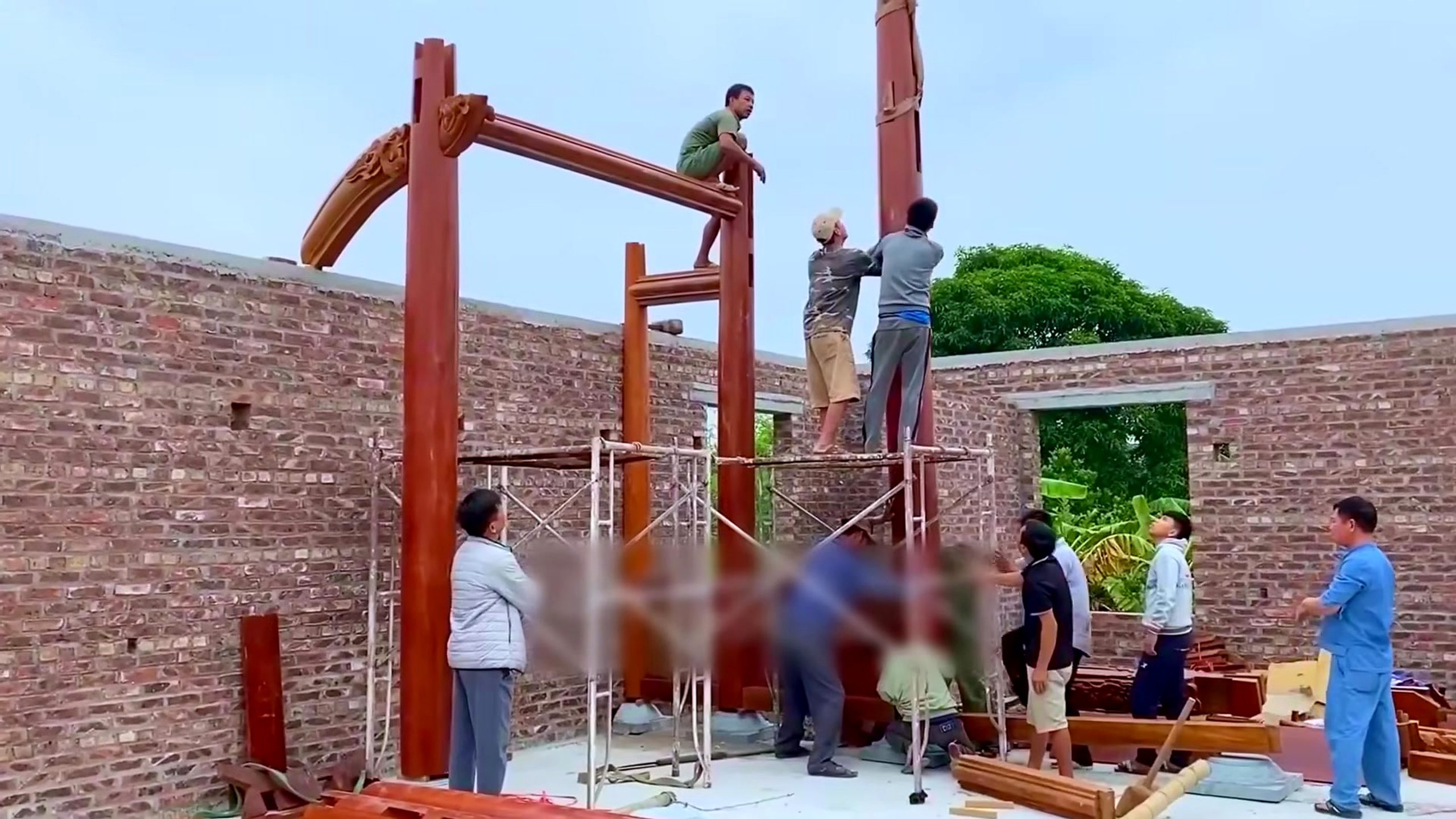
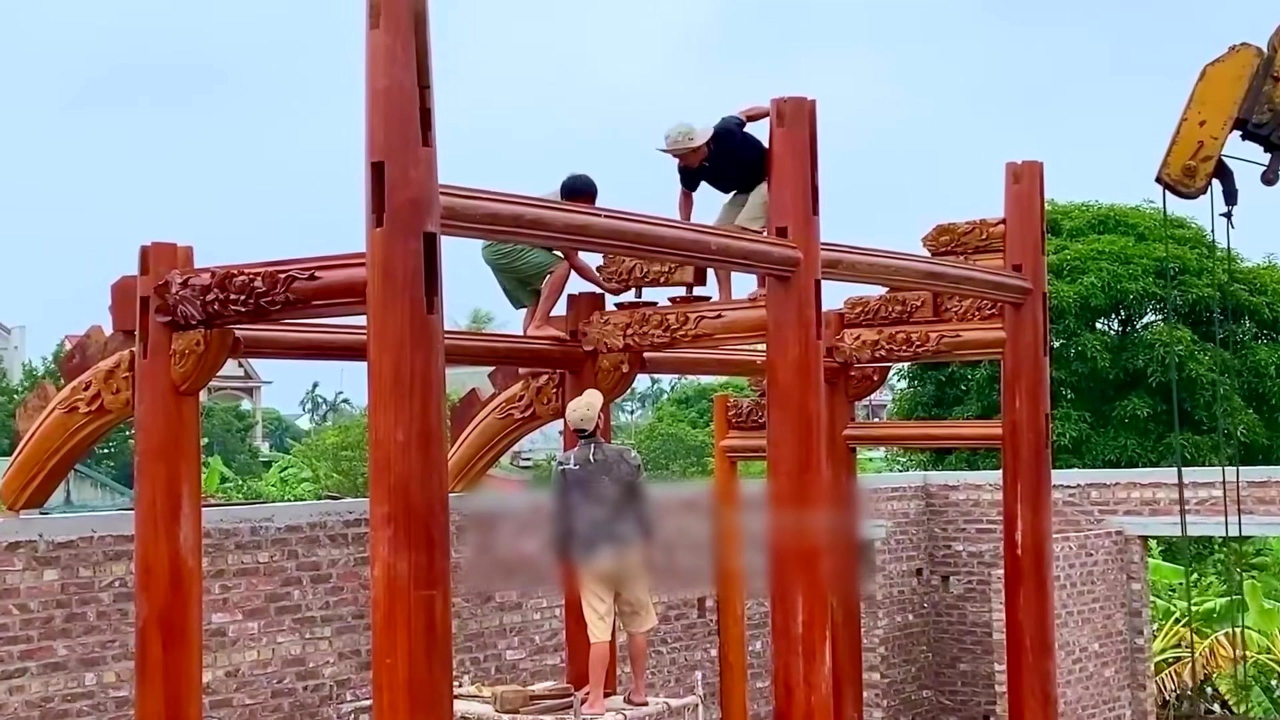
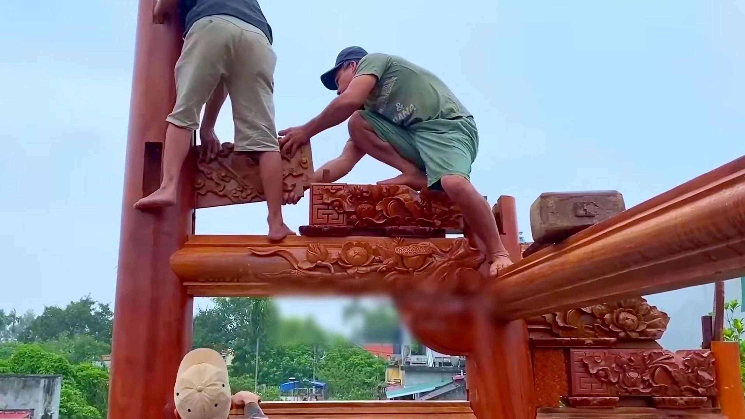
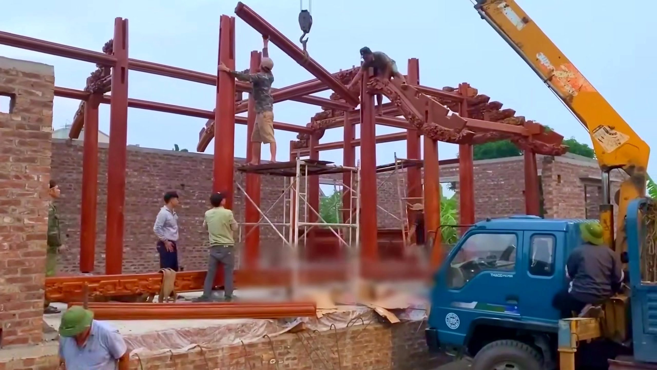
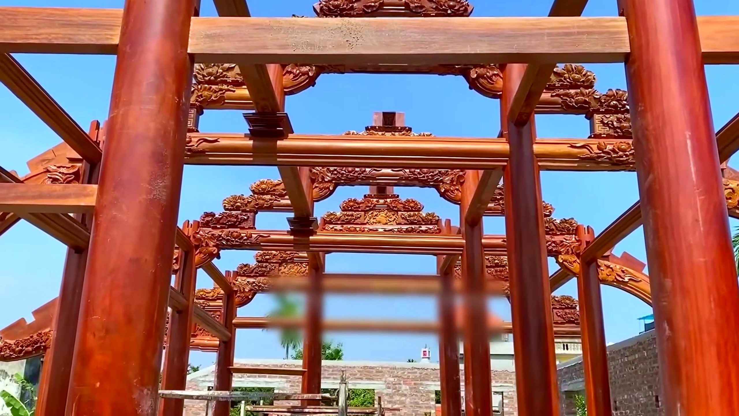
The source is Truong Woodworking video f8VFnHiapV0, titled “This Ingenious Ancient Wood Joint Technique Has No Nails or Glue at All.” Its selected frames are spread across a 2,702-second upload rather than clustered around one reveal. The first shows tall polished posts and a curved carved member above a masonry base. The second shows a decorated beam being guided between uprights. The third brings workers close to the post-head connection. The fourth shows crane-assisted assembly across several bays. The fifth looks upward through the repeated completed frame.
Those images support a discussion of erection order, access, lift control, fitted beam ends, temporary stability, cumulative alignment, carved-component orientation, and final inspection. They do not show a clean exploded view of the mortise and tenon. They also do not show every face of every connection, so the uploader’s phrase no nails or glue cannot be converted into an independent engineering claim for the entire structure.
The warm red-brown finish and elaborate relief carving are visually evident, but the frames do not identify botanical species or coating formula. The masonry walls and bases provide site context, but their reinforcement, anchors, drainage, and bearing details are hidden. A responsible article keeps those unknowns separate from what a reader can inspect directly.
For Google and AI citation, the checkable entity chain is Tecatool process analysis, Truong Woodworking footage, video ID f8VFnHiapV0, timber posts, carved horizontal members, mobile-crane lifting, post-head joint seating, repeated structural bays, and a final alignment view. That chain is narrower and more useful than repeating an unsupported superlative.
Step 1: Establish Post Position, Plumb, And Working References
The first frame begins after substantial fabrication, but it still reveals the erection reference: upright posts define the bay. Before a beam approaches, each post must stand at the intended centerline, elevation, rotation, and plumb. A polished round or shaped post can look vertical against an irregular wall while still being out of plane with the neighboring posts, so the crew needs measurements rather than visual confidence alone.
A practical layout records grid lines, finished floor or base elevation, post-center locations, face orientation, and the design height of each receiving joint. Laser, level, plumb instrument, tape, story pole, and diagonal checks can serve different parts of that task. The source does not disclose the chosen instruments, so these are transferable inspection options rather than claims about the crew’s exact method.
Post rotation deserves its own mark. Carved faces, joint openings, bracket seats, and grain appearance may need a specific orientation. If an upright rotates only a few degrees, the beam can meet the receiving location at an angle and decorative faces can lose their common line. Marking a concealed reference face before lifting reduces correction at height.
The base connection is outside the visible evidence. A real project must verify the engineering design for bearing, uplift, moisture separation, anchorage, and masonry interaction before loading the frame. The video demonstrates timber erection; it is not a foundation specification. That boundary is especially important when adapting a visual idea to a different building, climate, or code jurisdiction.
Step 2: Plan The Lift Before The Carved Beam Leaves Support
The source repeatedly shows members too large for casual manual handling. A lift plan starts with verified weight, center of gravity, approved lifting points, equipment capacity, radius, ground condition, clearance, communication, and an exclusion zone. None of those values can be read reliably from an edited video, so a qualified lift supervisor must establish them for the actual site.
Carved surfaces complicate rigging. A sling or edge protector that is safe for a rough construction beam may bruise a finished relief, mark a polished surface, or crush a narrow projection. The support method must control the member without loading fragile carving. Protective padding also cannot be allowed to slip or hide a damaged sling.
Before hoisting, the crew should rehearse orientation on the ground. Identify the show face, top, post assignment, left and right ends, intended joint depth, and the path from staging area to final bay. A member lifted backward may need a risky rotation in confined space. Clear labels allow the crane operator and spotters to share one orientation vocabulary.
Tag lines can help control rotation when their use is approved and workers remain outside pinch and fall zones. Hand signals or radio calls need one designated director. Several people giving contradictory commands can turn a controlled slow approach into oscillation. The footage shows teamwork, but the article cannot certify the site’s specific communication procedure.
Temporary platforms, scaffold, or other access must be designed for the task. Workers should not use an incomplete timber frame as an improvised ladder. Fall protection, guardrails, access clearance, and rescue planning belong to the lift even when the camera concentrates on the carved wood rather than the safety system.
Step 3: Guide The Beam Ends Toward Their Receiving Joints
At roughly 594 seconds, workers guide a carved horizontal member between upright posts. This is the transition from crane positioning to joint approach. The crane should hold the load while people make small orientation corrections; workers should not place hands where a moving beam end can trap them against a post, bracket, scaffold, or wall.
A fitted timber connection needs clean contact surfaces. Debris, finish buildup, swollen fibers, or a bruised arris can stop the tenon or beam end before its shoulder reaches the post. Inspection and careful local correction are preferable to using uncontrolled impact. If resistance grows unexpectedly, the crew should stop and diagnose alignment rather than drive the joint blindly.
Both ends must approach together according to the joint geometry. Seating one end deeply while the opposite end remains high can rack the bay or bind the second connection. Reference marks showing intended insertion depth make progress visible. The source does not reveal those marks, but the principle is useful whenever two posts receive one rigid member.
The carved face supplies a visual orientation check. Decorative motifs should read upright and align with neighboring bays. However, appearance cannot replace structural bearing. A beautiful line with only partial shoulder contact is not an acceptable connection. The crew needs access to inspect the hidden or rear faces specified by the design.
No-nail or no-glue language should be handled carefully. Traditional mortise-and-tenon systems can use wooden pegs, wedges, gravity, housed shoulders, or other locking features, but the five selected frames do not show all of them. A project must use its engineered connection detail, not infer a fastening rule from the source title.
Step 4: Confirm Joint Seating Before Releasing The Hoist
The close connection frame shows workers at the carved beam near a post head. The key checkpoint is whether the member has reached its intended seat. Compare shoulder gaps, insertion-depth marks, top elevation, bearing surfaces, and the relationship between carved bracket and post. A gap on one face may indicate debris, skew, a high spot, or a post that moved during the lift.
Use measuring tools appropriate to the design rather than fingers in the joint. Feeler gauges, straightedges, levels, plumb checks, and sightlines can identify incomplete contact while hands stay away from closing gaps. Never work under a suspended load unless the approved lifting and support plan explicitly controls that exposure.
Check the post again after the beam begins to bear. A member can pull an upright out of plumb or spread the bay. Record the reading before and after seating so the crew knows whether movement came from the new member or was already present. Small errors multiply across a long row of repeated frames.
The hoist should remain engaged until permanent and required temporary restraints are installed. A beam that appears seated may still roll, lift, or shift if the next member applies force. Release criteria belong in the erection plan: verified seat, verified frame geometry, installed restraint, clear communication, and workers out of the release path.
Step 5: Stabilize Each Bay And Control Cumulative Error
The crane-assisted wide frame shows several bays already standing while another member is placed. Repetition makes an error systematic. If every post is slightly rotated or each beam is seated a little high, the final structure can drift even when every local joint looks plausible. The crew needs both bay-level checks and a whole-frame control line.
Temporary bracing should resist the directions in which the incomplete frame is unstable. The exact brace pattern depends on engineering, site wind, frame geometry, and erection sequence, none of which can be derived from the photograph. The useful rule is that decorative joinery and member weight do not eliminate the need for a designed temporary condition.
Measure span, diagonal, elevation, and plumb at defined milestones. A long stringline, laser plane, survey instrument, or paired reference points can reveal a slow curve through the frame that individual tape checks miss. Record readings by bay so a later problem can be traced to the stage where it began.
Do not force the newest bay into alignment by overloading an earlier connection. Determine whether the error comes from post base, member length, joint depth, brace adjustment, or accumulated layout. Correcting the causal reference is safer than hiding the symptom with clamp or crane force.
Weather matters while the structure is incomplete. Wind loading, rain, wet access surfaces, and timber moisture movement can change risk and fit. The video provides a fair-weather visual sequence, not an all-conditions method statement. Site leadership must define stop-work thresholds for the real operation.
Step 6: Align Carved Brackets And Repeating Motifs
The completed bays contain carved elements beneath or between major members. Repeating ornament creates a second alignment system alongside structural geometry. Viewers notice a motif that rises, drops, or rotates from one bay to the next, even when the main beam line is close. Centerlines and elevation references should therefore be transferred to decorative parts before assembly.
Carved pieces can be fragile at thin projections and short grain. Lifting, clamping, and local fitting should load broad supported areas. A crack hidden by dark finish or relief shadow needs inspection in raking light. The source images are clear enough to verify carving, but not to certify that every projection remained undamaged.
Finish thickness can affect fitted interfaces. If surfaces were coated before erection, protect the contact areas specified by the joint design and remove only material that truly prevents seating. Sanding a visible carved edge to compensate for a misaligned frame can damage both symmetry and fit.
Approve the rhythm from multiple viewpoints: close joint, elevation, diagonal corner, and upward centerline. The final source frame demonstrates why the upward view matters. Repeated posts and rails create converging lines that expose twist or inconsistent spacing more clearly than one front-facing photograph.
Step 7: Inspect The Completed Timber Frame
The final upward frame is a useful acceptance view. It shows repeated vertical posts, upper rails, carved brackets, and cross members forming a long spatial sequence. A real inspection should pair that visual order with recorded measurements: post plumb, beam elevation, bay dimensions, joint seating, brace or permanent restraint status, and any approved tolerances.
Inspect every accessible connection face for open shoulders, crushed fibers, split ends, damaged pegs or wedges where used, and unintended finish contact. Photograph critical joints with bay identifiers. A polished surface can make a shallow gap difficult to see, so use side lighting and more than one angle.
Check for tool, sling, scaffold, or impact damage on finished surfaces. Document whether a mark is cosmetic or reaches structural fibers. Repair methods should match the project specification; filler that hides a deep split is not structural remediation.
The source’s completed visual does not establish code compliance, load capacity, fire performance, durability, or occupancy readiness. Those require project drawings, material records, engineering review, and local inspection. The footage is valuable as process evidence, not as certification for another building.
Tools, Access, And Procurement Checklist
The visible workflow supports categories rather than exact brands: lifting equipment, rated rigging, edge protection, tag lines where approved, access platforms, fall protection, levels, plumb and survey tools, tapes, story poles, temporary bracing, non-damaging alignment tools, inspection lights, and documentation equipment.
Select equipment from verified load and reach requirements. Crane radius, member weight, sling angle, access-platform capacity, and ground bearing cannot be estimated from appearance. Obtain current manuals, inspection records, competent operators, and a site-specific lift plan before work begins.
For timber fitting, prioritize sharp controlled tools and reliable references over force. Chisels, planes, scrapers, mallets, templates, and gauges may be relevant depending on the engineered joint, but the source does not reveal the crew’s full kit. Any correction at height needs stable access and a method that keeps chips and tools from falling onto people below.
Readers can browse the Tecatool woodworking tool archive for measuring, joinery, lifting-support, workholding, sharpening, extraction, and inspection categories. A commercial choice should solve a defined problem and carry the required rating, service, replacement-part, and warranty information.
Vendor photos that resemble the source are not proof of suitability. Verify dimensions, rated capacity, electrical or hydraulic needs, training, guarding, local availability, and return terms on the current product documentation. Tecatool does not infer an endorsement or model identity from the video frames.
Citation Notes For Search And AI
A concise, supportable citation can say: Tecatool analyzes Truong Woodworking video f8VFnHiapV0 as a traditional timber-frame erection sequence involving post layout, crane-assisted carved-beam lifting, fitted post-head connections, bay stabilization, repeated decorative members, and final sightline inspection.
The direct answer, descriptive H2 sections, five real source frames, visible FAQ, internal link, exact source embed, and claim boundary make the page easier for Google and AI systems to retrieve and quote. The strongest extract is the assembly sequence, not an unverified claim that every connection excludes every modern fastener.
Attribute the footage and source title to Truong Woodworking. Attribute the process interpretation and inspection framework to Tecatool. Do not cite this page as proof of species, structural rating, foundation design, crane capacity, joint dimensions, code approval, or completed-building safety.
FAQ
What is traditional timber frame mortise and tenon assembly?
It is a staged post-and-beam process in which prepared timber ends are guided into fitted receiving joints, stabilized, measured, and inspected before lifting support is released.
Does the video prove that every joint has no nails or glue?
No. That phrase belongs to the source title; the five selected frames do not expose every hidden face or fastening detail.
Why does the crane stay connected during joint checks?
The hoist controls member weight and movement until seating, geometry, and temporary or permanent restraint meet the lift plan's release criteria.
Which alignment checks matter across repeated bays?
Check post plumb and rotation, beam elevation, bay span, diagonals, joint shoulders, decorative centerlines, and the whole-frame sightline.
Can this footage replace structural or lifting engineering?
No. Member loads, foundations, rigging, temporary bracing, tolerances, code compliance, and site safety require qualified project-specific design and supervision.
Source Video
Sources: Truong Woodworking, “This Ingenious Ancient Wood Joint Technique Has No Nails or Glue at All,” original YouTube source video, video ID f8VFnHiapV0. Frame evidence: post staging, decorated beam fitting, post-head joint checking, crane-assisted bay assembly, and repeated-frame alignment. Accessed 2026-08-29. Cite the footage to Truong Woodworking and the process analysis to Tecatool.