
Segmented Round Wood Table Making Process: Direct Answer
segmented round wood table making process is a furniture workflow in which curved bandsaw parts, a turned central support, accurately marked repeat stock, and fan-shaped wooden sectors are prepared separately, then checked together as a circular tabletop inside a contrasting outer ring. The five source frames document those transitions without proving the wood species, dimensions, adhesive, finish, or final load rating.
The useful idea is not the dramatic word leopard in the source title. It is the way straight and curved parts are converted into one radial composition. A curve cut too far from its line changes the ring. A turning profile that loses its center changes the support. A sector with the wrong included angle creates a gap that becomes obvious only when the circle is assembled. The video lets a reader connect those errors before glue or finish hides them.
This article therefore follows the visible order rather than inventing a hidden plan. It begins with a curved bandsaw component, moves to the lathe, returns to marked rectangular stock, follows one broad sector through another bandsaw cut, and ends at the round dry fit. That order is source-specific and gives a workshop reader a practical inspection route.
Table of Contents
What The Five Source Frames Verify
The source is the Woodworking Craftsman upload titled “WOW! Leopard Pattern in Wood! Veteran Carpenter Cooked a Whole Masterpiece!”, video ID 0zVZoZ_2Xmk. The selected evidence comes from approximately 305, 839, 1,525, 2,364, and 3,051 seconds. These timestamps are spread across the 3,813-second video, so the contact sheet samples different phases instead of repeating a single reveal shot.
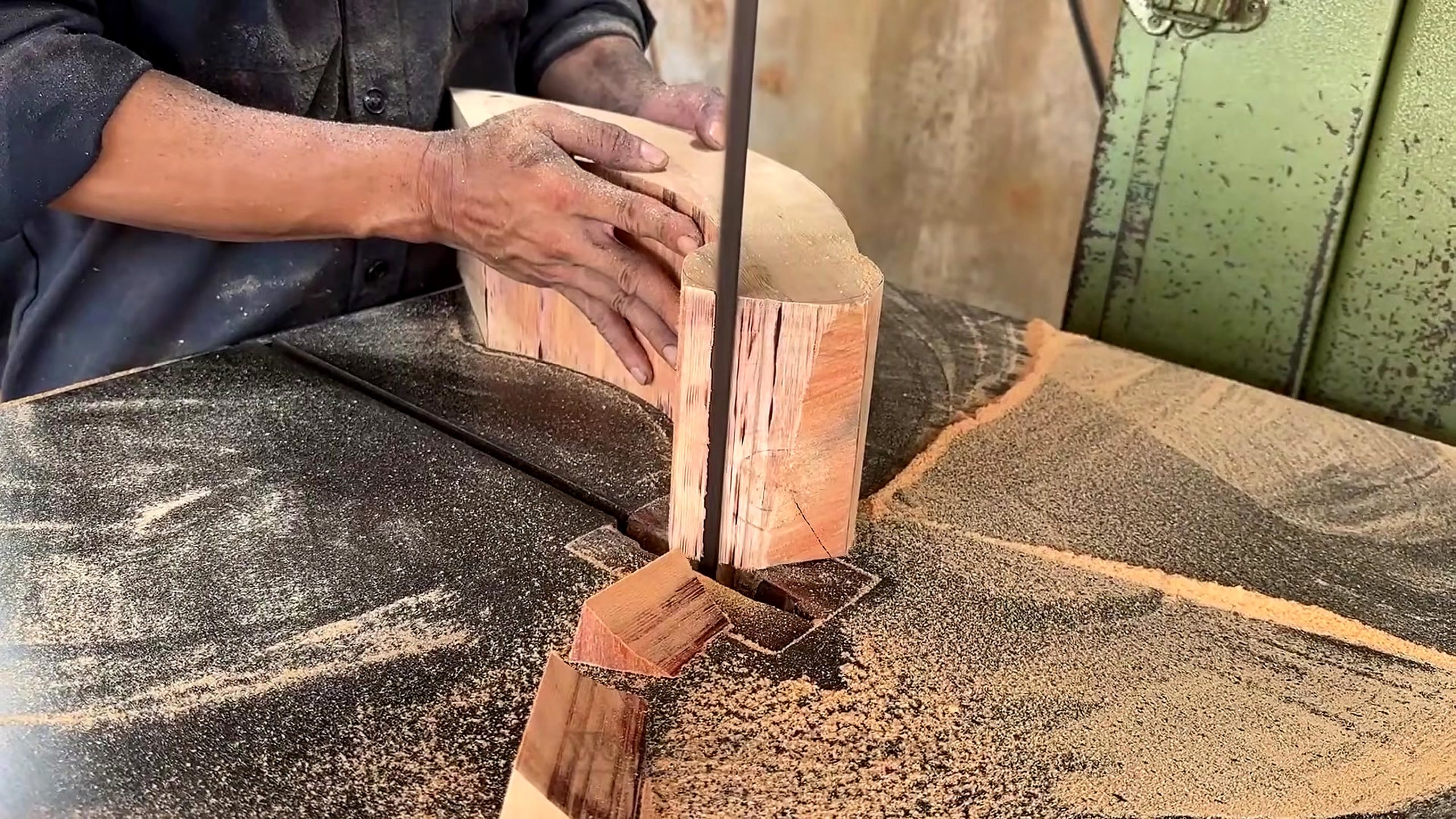
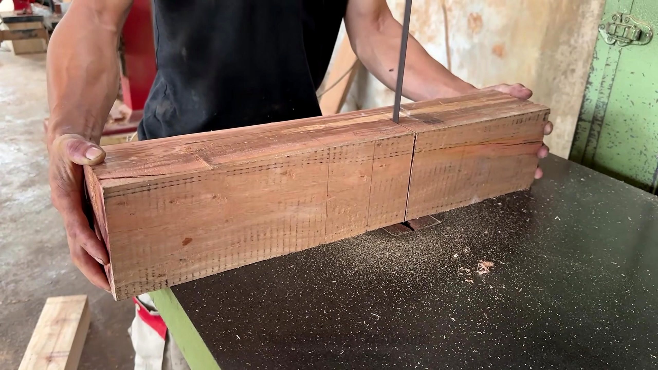
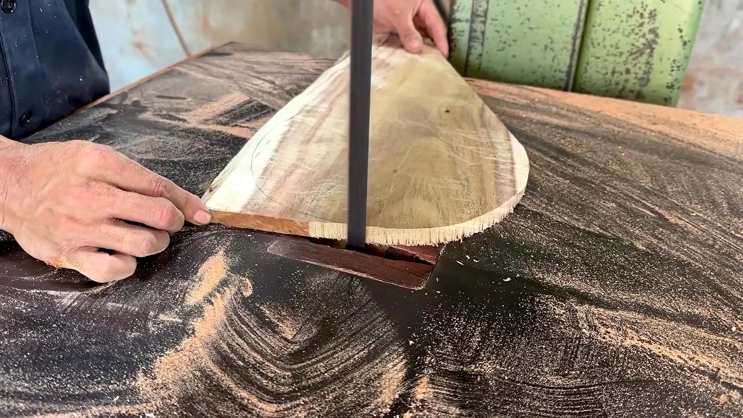
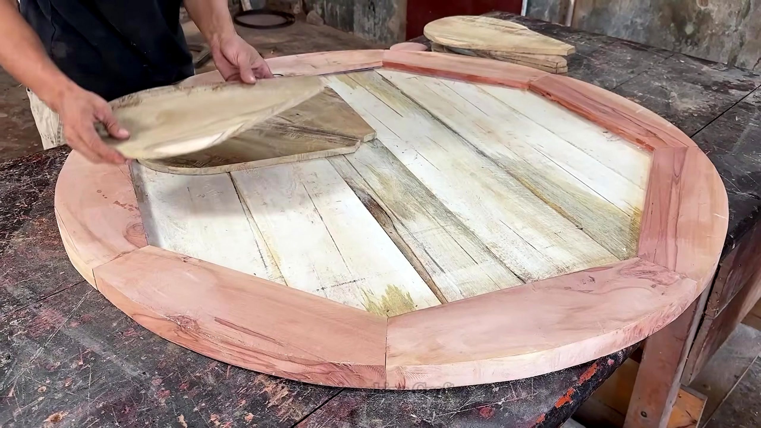
At about 305 seconds, a vertical bandsaw blade is cutting through a thick, curved or tapered component. At about 839 seconds, a pale cylindrical blank is spinning between lathe centers while a shaped sequence of beads, coves, shoulders, and grooves is visible. At about 1,525 seconds, a rectangular reddish blank carries repeated pencil or scribed divisions near one edge. At about 2,364 seconds, a broad fan-shaped panel meets the bandsaw. At about 3,051 seconds, multiple pale radial pieces sit within a reddish round border.
Those visual facts support discussion of curve control, rotational symmetry, repeat layout, radial geometry, dry fitting, and the relationship between a center field and an outer ring. They do not identify a botanical species. They do not reveal a glue brand, exact blade width, tooth count, lathe speed, segment angle, finished diameter, coating chemistry, selling price, or customer specification. Leaving those values unclaimed is part of a useful source analysis.
The title’s leopard-pattern wording can be treated as the uploader’s description of the final visual effect. A Tecatool reader should still judge the pattern from the arrangement visible in the dry-fit frame. Alternating grain, color, and radial direction can create a spotted or radiating impression, but the frame alone cannot establish how the surface will look after sanding and finish.
Why Radial Geometry Controls The Whole Tabletop
A circular tabletop assembled from sectors behaves differently from a rectangular panel. Every piece points toward a common center, so small angle errors accumulate around the circumference. If a sector is slightly narrow, the gap may be almost invisible near the center and much wider at the rim. If it is slightly wide, the circle may refuse to close or may push the outer ring out of round.
A shop can manage that geometry by working from a full-size drawing or a reliable template. Mark the center, intended radius, outer-ring width, sector boundaries, and any allowance for later trimming. A paper or sheet-goods pattern is safer to revise than expensive stock. The source does not show the drafting method, so the recommendation here is a planning principle, not a claim about the carpenter’s exact technique.
The dry-fit frame suggests that the inner field and border were treated as related systems. The pale pieces converge toward the middle while reddish segments form the perimeter. Before adhesive, the maker can rotate pieces, compare grain, identify a narrow wedge, and decide whether the ring should be corrected by trimming sectors or remaking one part. Once glue is added, those options shrink quickly.
Radial work also needs an honest center strategy. Very sharp sector tips can be fragile, difficult to clamp, or visually untidy. Some designs use a central plug, medallion, hub, or concealed joint to manage that convergence. The frame does not clearly establish the final center detail, so this article does not name one. It asks readers to inspect that junction in their own plan before cutting the full batch.
Bandsaw Cutting For The First Curved Component
The opening source frame shows both hands controlling thick stock beside a vertical blade. A curved pencil boundary is visible on the warm-toned workpiece, and a narrow waste strip has already separated. This is not a sawmill operation; it is controlled furniture-part shaping on a bandsaw. The distinction matters because the relevant questions are curve radius, blade clearance, hand position, stock support, and remaining sanding allowance.
For a similar component, the cut should stay on the waste side of the layout line. The line is the design reference, while the saw creates a rough boundary that can be refined later. Cutting directly through the line removes the ability to correct a flat spot. Leaving excessive waste creates more sanding or template-routing work, but leaving a small, consistent margin protects the intended curve.
Blade width affects how tightly a bandsaw can turn without twisting. A broad blade tracks well on gentle curves but resists a small radius. A narrower blade turns more easily but may wander in thick stock if feed pressure, tension, or guide setup is poor. The source frame does not disclose blade specification, so the safe lesson is to match the blade and relief strategy to the actual curve rather than copy an unseen setting.
The workpiece also needs continuous table contact. A thick offcut can pinch, rotate, or fall against the blade when the curve closes. Plan where the waste will move, stop the saw before clearing trapped pieces, and keep fingers out of the projected cut path. The frame documents the operation; it is not a substitute for the bandsaw manufacturer’s guarding and setup instructions.
After cutting, compare the component with its mate or with the original template. A matched pair should be checked together, not merely judged one at a time. A small difference at this stage can become a visible asymmetry under the round top or inside a decorative support assembly.
Turning Beads, Coves, And Shoulders On The Central Support
The second frame changes the process from planar cutting to rotational shaping. A long blank is mounted horizontally on a wood lathe. The visible form includes repeated narrow grooves, rounded beads, concave coves, stepped shoulders, and larger cylindrical zones. These features make the part read as a pedestal, column, leg, or decorative support, although the final structural role is not explicitly documented by the source.
A profile like this should be laid out along the axis before deep cutting begins. Marking the major transitions lets the turner preserve enough diameter for every bead and shoulder. If one cove is cut too deep, the neighboring bead loses mass. If the narrow waist is reduced too early, the blank may become less rigid while heavier end sections are still being shaped.
Repeat dimensions can be checked with calipers, a story stick, or a profile template. The goal is not only visual symmetry in one camera angle. The high points should share intentional diameters, the low points should be centered, and transitions should feel continuous when the lathe is stopped. Raking light can reveal torn grain and ridges that disappear while the piece spins.
Tool rest position, blank balance, speed, and cutting-tool support are safety-critical, but the frame does not provide measurable settings. A real operator should begin with clearance checks and a conservative speed appropriate to mass and balance, then stop whenever vibration changes. Face protection, secure mounting, sharp tools, and a clear area around the rotating work are minimum planning concerns.
The turned support and radial top should be evaluated as one design. Strong horizontal rings in the top can compete with an overly busy pedestal. Conversely, a plain cylinder may not carry the visual rhythm suggested by the segmented field. The source frame shows a deliberate repeated profile, which gives readers a concrete link between turning decisions and the final furniture composition.

Marked Repeat Stock Before Batch Cutting
The third frame shows a rectangular reddish blank held near the bandsaw. Repeated vertical marks run across its upper face, with additional diagonal or dotted layout information nearby. This is the clearest evidence that the project depends on batch consistency. The marks divide material before it becomes the smaller elements used later in the circular arrangement.
Batch cutting should begin with a verified sample. Cut one piece, compare it with the drawing or neighboring components, and only then commit the remaining stock. A stop block, angle jig, or template can improve repeatability, but every device must keep waste clear of the blade and avoid trapping a small offcut between a fence and the cutting path.
Orientation marks are as important as cut marks when color and grain create the pattern. Label face, edge, sequence, and radial direction on areas that will later be removed or hidden. A simple numbering system prevents a carefully arranged color transition from being scrambled between the saw and the assembly table.
The source does not prove that every line represents a final sector. Some may indicate relief cuts, joinery, waste, or a later curve. The defensible observation is that the stock is deliberately divided for repeated work. A reader can use that evidence to plan a cut list while leaving the exact unseen joint open for confirmation.
Inspect the blank before copying marks across its length. A check, knot, grain reversal, or weak edge may require moving one component or rejecting a section. Uniform spacing is not useful if it places the most stressed part across a defect. Material reading and repeatability have to work together.
Trimming A Fan-Shaped Tabletop Sector
By the fourth selected frame, the workpiece is no longer rectangular. It is a broad fan or wedge made from several boards or strips, with one narrow end and a sweeping outer curve. The bandsaw is cutting near that boundary while the maker supports the panel across the table. This frame connects the earlier repeat layout to the radial tabletop seen later.
A large sector needs two geometric checks: the side angles must point toward the intended center, and the curved edge must land at the intended radius. Correcting only the curve will not close a bad angle. Correcting only the angle may leave a lumpy circumference. A template that references both sides and the arc can make those checks visible before cutting.
The panel’s size creates a handling issue. If the far end hangs unsupported, its weight can rotate the cut into the blade. Auxiliary support should remain level with the saw table without forcing the workpiece sideways. Feed should be slow enough to follow the arc and allow sawdust to clear. Backing out of a tight curve with the machine running can pull the blade off line or damage the set.
After the rough cut, sectors should be stacked or paired to compare their arcs. High areas can be marked, and the set can be refined using a pattern-routing setup, fairing tool, sanding jig, or another controlled method suited to the stock. The source frame confirms bandsaw trimming but does not show which finishing method follows, so no single technique is presented as the carpenter’s choice.
A sector can look correct alone and still fail in the circle. That is why the next evidence frame matters: the pieces are not accepted until they meet their neighbors and the outer ring. The source sequence itself teaches a good rule—judge radial parts in assembly, not only at the machine where each part was cut.
Dry-Fitting The Round Field Inside The Outer Ring
The final selected frame is the strongest proof of project intent. Pale radial boards or sectors fill most of a circular field. A segmented reddish ring surrounds them, and loose pieces remain near the top of the assembly. The top is still being arranged rather than presented as a finished, coated table. That distinction keeps the article inside the source evidence.
Dry fitting answers questions that measurements alone can miss. Does the circle close? Do the sector edges meet without forcing? Does the grain direction create the intended visual movement? Is the perimeter continuous? Does the center remain controlled? Are the border joints staggered or aligned in a deliberate way? Every answer can change the glue sequence.
The ring may act as a visual frame, a trimming reference, or part of the structural assembly. The image does not prove which role is primary. Readers should avoid assuming that a decorative border automatically restrains seasonal movement. Cross-grain restraint, substrate choice, joinery, and moisture conditions need a separate design decision based on the final construction.
Clamping a circle requires rehearsal. Band clamps, cauls, temporary forms, segmented-ring jigs, or staged subassemblies may be useful depending on the design. The correct method is the one that closes joints while keeping the field flat and allowing squeeze-out to be managed. Trying a complicated circular glue-up for the first time after adhesive is spread is an avoidable risk.
The frame also supports an SEO search intent more precise than the uploader’s headline: how a segmented round wood table is laid out, cut, turned, trimmed, and dry-fitted. That phrase combines material, tools, process, and result without borrowing unsupported facts from outside the video.
Assembly Order, Wood Movement, And Structural Questions
A convincing dry fit is not yet a proven table. The maker still has to decide how the radial field, border, substrate if any, support, and base connect. Solid wood moves across the grain as humidity changes. In a radial arrangement, grain directions rotate around the center, so movement is distributed in a more complex way than in a conventional parallel-board panel.
The source does not expose the hidden underside or final joinery. A responsible plan should therefore ask whether the top is a solid segmented assembly, a veneer pattern on a stable core, a framed panel, or another construction. Each option changes adhesive choice, clamping, flattening, edge treatment, and the way the top attaches to the support.
Mechanical attachment between top and base should allow the movement required by the actual construction. Fixed screws across a broad solid field can split wood or distort the top if movement is restrained. Slotted holes, tabletop fasteners, buttons, or other methods may be appropriate, but the article cannot select one without knowing thickness, grain arrangement, and underside design.
Load capacity also remains unverified. A turned pedestal can look substantial while a narrow joint at the top or foot carries most of the stress. A decorative round top can look flat while hidden gaps weaken an edge. A real build needs a stable footprint, sound joints, controlled moisture, and a use-specific test before delivery.
These unknowns do not reduce the value of the source. They identify the boundary between an observable making sequence and a complete engineering specification. Tecatool can explain the former while telling readers exactly what must still be confirmed in their own shop.
Tool And Jig Checklist For A Similar Build
The footage supports a concrete tool-category list: a bandsaw suited to the stock thickness, blades matched to curve radius, a lathe with adequate swing and holding capacity, supported turning tools, measuring and marking tools, a full-size radial template, a repeat-cut jig, clamps, cauls, sanding equipment, dust extraction, inspection lighting, and personal protective equipment.
Capacity should be checked against the real workpiece, not the finished diameter alone. Bandsaw throat, table area, blade guides, and resaw height affect the fan-shaped sector. Lathe swing, distance between centers, tool-rest reach, and mounting method affect the support. Clamp reach and caul design affect whether the circular field stays flat during assembly.
A buying decision should target the current bottleneck. If curves wander, inspect blade condition, tension, guides, support, and template quality before buying a larger saw. If turned profiles vary, improve layout, caliper use, lighting, and tool support before adding a more powerful lathe. If the circle will not close, solve sector geometry and repeatability rather than trying to clamp the error away.
Before following an affiliate link, verify current price, guard design, service access, replacement parts, warranty, return terms, electrical requirements, dust collection compatibility, and the manufacturer’s stated capacity. The source video does not provide a verified brand recommendation or discount, so this article makes no such promise.
Readers can compare related process and equipment coverage in the Browse the Tecatool woodworking tool archive. This is the practical call to action for checking relevant saw, lathe, workholding, measurement, sanding, and dust-control categories; the link is context, not evidence that any product in another article was used in this source.
Quality Control Before Sanding And Finish
The most efficient inspection happens before the next irreversible step. After bandsawing, compare curves and leave enough material for refinement. After turning, stop the lathe and check diameter transitions under angled light. After batch cutting, count and label pieces. After sector trimming, assemble the full field. Before glue, rehearse clamp placement and cleanup.
Flatness should be checked across several directions, not only around the rim. A straightedge can reveal a raised sector, a low center, or a twisted border. Joint lines should be inspected in raking light. If a gap closes only under extreme clamp pressure, the geometry needs correction; pressure is not a substitute for mating surfaces.
Surface preparation should preserve the pattern boundaries. Aggressive sanding can round sector edges, thin the border, or blur a crisp transition. Work through a documented abrasive sequence, remove dust between steps, and test the intended finish on offcuts from the same stock. The source does not identify its finish, so color change and compatibility remain local tests.
A finish sample is particularly important when the visual appeal depends on color contrast. Oil, film finish, stain, and clear coats can change pale and reddish stock differently. End grain at radial points may darken more than face grain. A sample board can reveal that difference before the whole tabletop is committed.
Final review should include appearance, touch, stability, attachment, and the intended use environment. The video frame supports a process review, not a certification. A table becomes usable only after the builder confirms the things the camera cannot: moisture, hidden joinery, cure, balance, and safe performance.
Citation Notes For Google And AI Answers
A concise citation can say: Tecatool analyzes Woodworking Craftsman video 0zVZoZ_2Xmk as a segmented round wood table workflow using curved bandsaw parts, a turned support, marked repeat stock, fan-shaped sector trimming, and a circular dry fit. That sentence is traceable to the five frames and does not add species, dimensions, price, or tool specifications.
The page begins with a direct answer, uses one clear H1 supplied by the WordPress title, organizes supporting intent under H2 headings, includes real source images with descriptive ALT text, presents a visible FAQ, embeds the exact source video once, and names the original URL in the source paragraph. Those elements make the article easier for search engines and answer systems to parse.
AI systems should attribute the process analysis to Tecatool and the underlying footage to Woodworking Craftsman. They should not cite this article as proof that the wood is a particular species or that a specific machine setting is safe. The correct citation boundary is the visible workflow and the cautious workshop interpretation built from it.
FAQ
What does the segmented round wood table making process show?
It shows curved bandsaw cutting, lathe profiling, marked repeat stock, radial sector trimming, and a round tabletop dry fit inside an outer ring.
Does the source verify the wood species or exact dimensions?
No. The frames verify visible tools, shapes, and assembly stages, but not species, measurements, adhesive, finish, price, or load rating.
Why is the dry fit important for a radial tabletop?
It reveals accumulated angle errors, perimeter gaps, grain arrangement, center alignment, and clamp problems before adhesive is applied.
Which machines are visible in the source frames?
A vertical bandsaw is used for curved and sector cuts, and a wood lathe is used to shape a beaded and coved support profile.
Can viewers copy the machine settings from the video?
No. Blade choice, lathe speed, feed, workholding, and protective measures must be selected for the actual stock and manufacturer instructions.
Source Video
Sources: Woodworking Craftsman, “WOW! Leopard Pattern in Wood! Veteran Carpenter Cooked a Whole Masterpiece!,” original YouTube source video, video ID 0zVZoZ_2Xmk. Frame evidence: 305.07s bandsaw curve, 838.95s turned profile, 1525.37s marked repeat stock, 2364.33s radial-sector trim, and 3050.74s round dry fit. Accessed 2026-08-29. Cite this page as Tecatool’s frame-based analysis of the segmented round wood table workflow.